Research contents
2.1.2 Measurement technique for void fraction of capacitance type
(1) Introduction
As a measurement method of the void fraction which shows the rate of the void occupied in fluid, the capacitance measuring method was developed to the conventional electric resistance measuring method. This method is not dependent on water qualit and measurable to the condition from 100% of liquid to 100% of gas.
A high frequency power supply is impressed to a couple of electrodes. Then, the capacitance in the two-phase flow which flows between a couple of electrodes is measured. This result is converted into the void fraction using a measurement characteristic formula.
(2) Measurement principle
When investigated under the conditions of the atmospheric pressure and the high temperature and pressure, it was found that the relation of the void fraction and the electric resistance (the resistance ingredient R, the capacitance ingredient C) show the fixed measurement characteristic (i.e., hyperbola function).
Then, the void fraction is obtained by proofreading measured value using this relation. Constant voltage exchange is impressed to a couple of electrodes which are installed by facing each other in a two-phase flow channel. The void fraction is calculated by measuring the electric resistance in the two-phase flow which flows between two electrodes.
(3) Fundamental characteristic experiment
1) Atmospheric pressure experiment
The void fraction in the two-phase flow which flows between two electrodes was investigated using a 4x4 bundle experimental setup which simulates a part of the BWR fuel bundle. A couple of electrodes are settled as shown in Fig. 2.3.2.1.
2) High temperature and pressure experiment
The void fraction in the two-phase flow which flows between two electrodes was measured using a 37 fuel bundle experimental setup. Two electrodes were attached in the position on both sides of a vessel in the horizontal direction as shown in Fig. 2.3.2.2.
(4) Experimental results
1) Atmospheric pressure experiment
The result measured with the 4x4 bundle experimental setup is shown in Fig. 2.3.2.3. A vertical axis shows non-dimension current. Here, 0 means the liquid phase of 100%, and then, 1 expresses the gas phase of 100%. A horizontal axis shows the void fraction.
In Fig. 2.3.2.3, a black circle shows the C ingredient, the white circle presents the R ingredient, and the solid line shows the result from Maxwell equation. Since the measurement results were well in agreement with the Maxwell equation, the measured electric signals were converted into the void fraction using this equation.
2) High temperature high-pressure examination
At the pressure condition of 2MPa, the void fraction in the 37 fuel bundle experimental setup was measured. The relation between the void fraction and quality is shown in Fig. 2.3.2.4. Here, the quality shows the ratio of the mass flux of vapor and the mass flux of water and vapor. From the experiment, it was found that the quality decreases as increasing the flow rate..
(5) Summary
The developed measurement technique is possibe to measure the void fraction from the liquid phase of 100% to the gas phase of 100%, which was difficult by the conventional measuring method. Therefore, a wide range use with this measurement technique is considered as a new two-phase flow measurement technique.
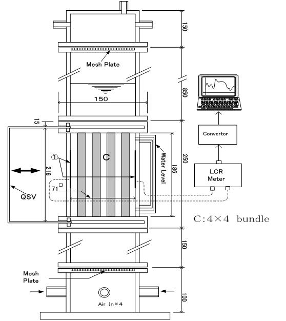
Fig. 2.3.2.1 The way to settle a couple of electrodes in 4x4 rod bundle
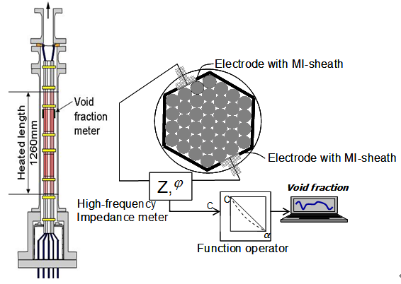
Fig. 2.3.2.2 The way to settle a couple of electrodes in 37 rod bundle
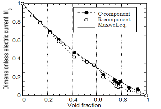
FIg. 2.3.2.3 Correlation between measured void fraction and characteristic correlation
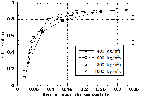
Fig. 2.3.2.4 Correlation between void fraction and flow rate